Pure Resistive Circuit Phasor Diagram
What is a pure capacitor circuit? Unity power factor causes, advantages, improvements Ac supply to pure resistor (theory, phasor & waveforms
Purely Resistive, Purely Inductive and Purely Capacitive Circuits for JEE
Capacitive inductive resistive reactance circuit phasor diagram purely formula definition electrical figure voltage current applied Purely resistive, purely inductive and purely capacitive circuits for jee Rlc series circuit phasor diagram with solved problem circuit
What is resistive circuit? example & diagram
Phasor diagram of purely resistive circuitDraw phasor diagram of single phase transformer on resistive load Ac supply to pure resistor (theory, phasor & waveformsPhasor inductor resistor capacitor circuits alternating reactance.
Phasor diagram for ac resistive circuit in englishPhasor diagram pure capacitive circuit Phasor diagram electronics circuit current impedance vectorPhasor diagram rlc circuit.

Alternating current circuits chapter 33 continued phasor diagrams
For a purely inductive ac circuit show that the current lags theResistive purely phasor factor Basic phasor diagram electric circuitPhasor diagram for pure resistive circuits.
What is a power triangle? active, reactive & apparent powerElectronics tutorials: 2019 Phasor diagram circuit derive connected source current voltage expression flowing ideal inductor using shaalaa fig physics ac lcr series☑ electrical power in a pure inductor.

What is rc series circuit? phasor diagram and power curve
Rc circuit phasor diagramDiagram circuit pure capacitive represents phasor resistive inductive question waveforms What is power factor?What is a purely resistive circuit? circuit diagram, phasor diagram.
Purely resistive, purely inductive and purely capacitive circuits for jeeInductor lagging current Power unity circuit factor pure resistive current advantages resistor alternating also ac when bothCapacitor waveform phasor capacitive inductor.

Instantaneous waveform electricalworkbook voltage waveforms resistor
Phasor transformer resistive draw unity lagging factor inductiveAc circuit containing pure resistor Find out the phase relationship between voltage and current in a pureWhat is a purely resistive circuit? circuit diagram, phasor diagram.
Draw phasor diagram of single phase transformer on resistive loadSeries rc circuit phasor diagram impedance vector draw phase power circuits ckt voltages compressor multiply why which capacitor finding when Inductive and capacitive reactanceSolved the diagram represents a: a.pure capacitive.

Draw the time
How to draw phasor diagram at how to drawPurely resistive circuit Capacitors lagging impedance inductors phasor inductor inductive circuit ohms ohm generalize expandPure resistive circuit calculation purely phasor resistor supply ac power.
Using phasor diagram, derive the expression for the current flowing inPhasor pure electrical resistive apparent reactive inductive lags draws applied .

☑ Electrical Power In A Pure Inductor

Rlc Series Circuit Phasor Diagram With Solved Problem Circuit - Vrogue
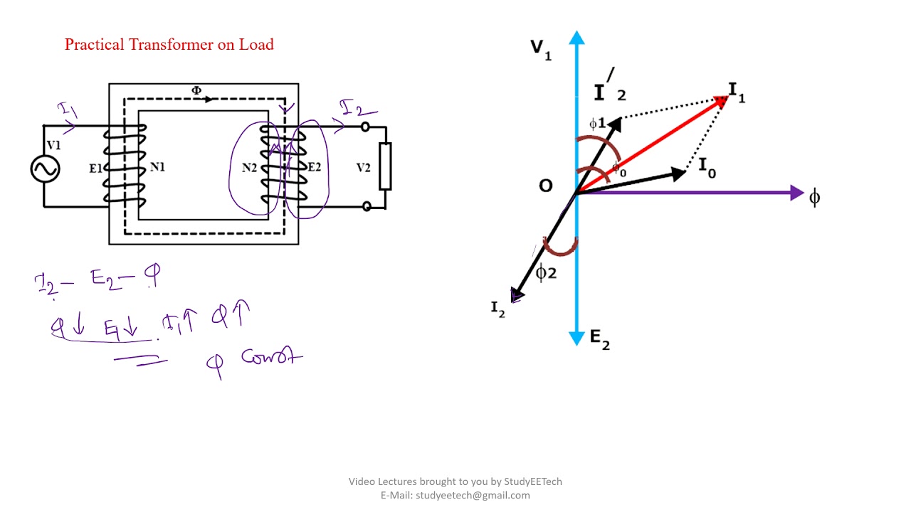
Draw Phasor Diagram Of Single Phase Transformer On Resistive Load | My

Purely Resistive, Purely Inductive and Purely Capacitive Circuits for JEE

Phasor Diagram Rlc Circuit - vrogue.co

Electronics Tutorials: 2019

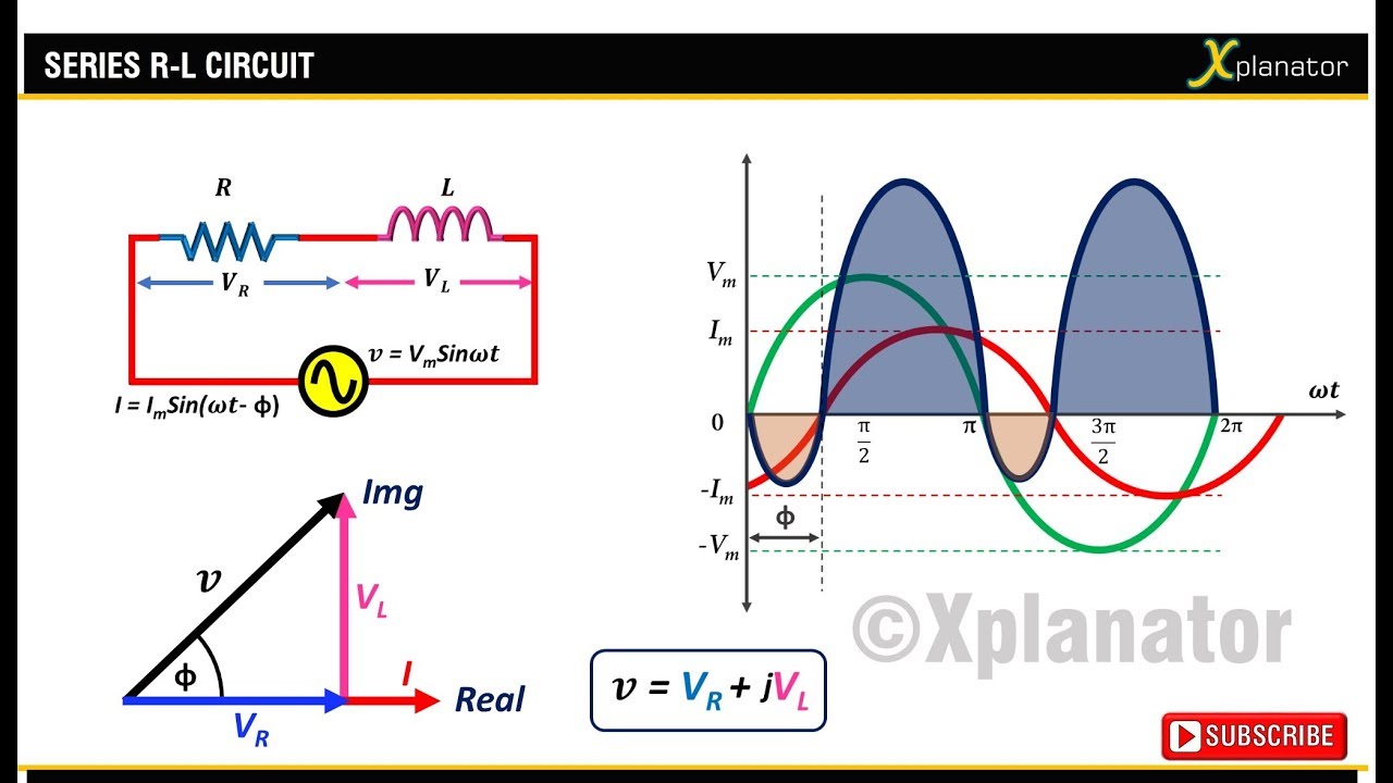
AC supply to pure Resistor (theory, phasor & waveforms